
Publié par Prof. Jean DEMARTINI sous licence Creative Commons BY-SA.
Le développement de procédures synchrones sur Arduino n’est pas très facile. La bibliothèque de base ne permet pas de réaliser des horloges logicielles non-bloquantes pour déclencher des actions associées à différentes périodes d’échantillonnage. De telles horloges permettent une programmation « event-driven synchrone » non bloquante. Un autre article montrera comment réaliser une programmation « event-driven asynchrone » déterministe non bloquante.
Cahier des charges
Une horloge software est caractérisée par :
- une période (ici en millisecondes) déclenchant des « tics » (événements d’horloge) à intervalles réguliers,
- une phase (en millisecondes) avant le premier « tic »,
- une fonction de callback (action périodique) dont l’appel est déclenché à chaque « tic ».
Implémentation
/***
 * Implementation of software clocks based on
 * the system clock millis().
 *
 * That idea can be extended to faster software clocks based
 * on the system clock micros().
 ***/
class Clock {
  private:
    unsigned int  phase;
    unsigned int  period;
    unsigned long counter;
    void (*callback)(void);
  public:
    void setup(int, int, void(*)(void));
    int  tick(void);
};

void
Clock::setup(int p, int f, void (*cb)(void)) {
  period = p;
  phase = f;
  counter = millis();
  callback = cb;
}

int
Clock::tick() {
  int s = (millis() - counter) > phase;
  if (s) {
    /***
     * the clock event triggers.
     * the callback function.
     ***/
    phase = period;
    counter = millis();
    callback();
    return 1;
  }
  return 0;
}
Exemple d’application
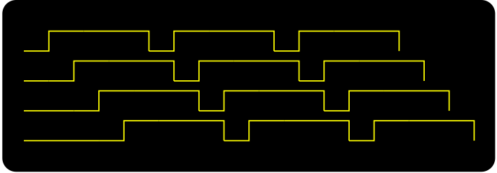
La commande d’un moteur pas à pas nécessite de créer des signaux de commande périodiques mais déphasés.
/***
 * Producing the 4 phases for a step motor control.
 ***/
...
const int ledPin1 = 13;
const int ledPin2 = 7;
const int ledPin3 = 8;
const int ledPin4 = 9;

Clock c1, c2, c3, c4;

/***
 * callback functions
 */
void blink1() { digitalWrite(ledPin1, !digitalRead(ledPin1)); }
void blink2() { digitalWrite(ledPin2, !digitalRead(ledPin2)); }
void blink3() { digitalWrite(ledPin3, !digitalRead(ledPin3)); }
void blink4() { digitalWrite(ledPin4, !digitalRead(ledPin4)); }

void setup() {
  pinMode(ledPin1, OUTPUT);
  pinMode(ledPin2, OUTPUT);
  pinMode(ledPin3, OUTPUT);
  pinMode(ledPin4, OUTPUT);

  digitalWrite(ledPin1, LOW);
  digitalWrite(ledPin2, LOW);
  digitalWrite(ledPin3, LOW);
  digitalWrite(ledPin4, LOW);

  /***
   * Building of the different clocks.
   * The callback functions are activated.
   */
  c1.setup(5, 1, &blink1);
  c2.setup(5, 2, &blink2);
  c3.setup(5, 3, &blink3);
  c4.setup(5, 4, &blink4);
}

void loop() {
  /***
   *  put here a call to the tick method of each clocks.
   *  When time of period elapse, the callback function
   *  is automatically called.
   *
   *  Its a kind of clocked software interrupts.
   *
   *  It is possible to use a master hardware clock to tick all the other ones.
   */
  c1.tick();
  c2.tick();
  c3.tick();
  c4.tick();

  ... /*** main part of the application ***/
}
En rassemblant toutes les parties
/***
 * Implementation of software clocks based on
 * the system clock millis().
 *
 * That idea can be extended to faster software clocks based
 * on the system clock micros().
 ***/
const int ledPin1 = 13;
const int ledPin2 = 7;
const int ledPin3 = 8;
const int ledPin4 = 9;

class Clock {
  private:
    unsigned int  phase;
    unsigned int  period;
    unsigned long counter;
    void (*callback)(void);
  public:
    void setup(int, int, void(*)(void));
    int  tick(void);
};

void
Clock::setup(int p, int f, void (*cb)(void)) {
  period = p;
  phase = f;
  counter = millis();
  callback = cb;
}

int
Clock::tick() {
  int s = (millis() - counter) > phase;
  if (s) {
    /***
     * the clock event triggers.
     * the callback function.
     ***/
    phase = period;
    counter = millis();
    callback();
    return 1;
  }
  return 0;
}

Clock c1, c2, c3, c4;

/***
 * callback functions
 */
void blink1() { digitalWrite(ledPin1, !digitalRead(ledPin1)); }
void blink2() { digitalWrite(ledPin2, !digitalRead(ledPin2)); }
void blink3() { digitalWrite(ledPin3, !digitalRead(ledPin3)); }
void blink4() { digitalWrite(ledPin4, !digitalRead(ledPin4)); }

void setup() {
  pinMode(ledPin1, OUTPUT);
  pinMode(ledPin2, OUTPUT);
  pinMode(ledPin3, OUTPUT);
  pinMode(ledPin4, OUTPUT);

  digitalWrite(ledPin1, LOW);
  digitalWrite(ledPin2, LOW);
  digitalWrite(ledPin3, LOW);
  digitalWrite(ledPin4, LOW);

  /***
   * Building of the different clocks.
   * The callback functions are activated.
   */
  c1.setup(5, 1, &blink1);
  c2.setup(5, 2, &blink2);
  c3.setup(5, 3, &blink3);
  c4.setup(5, 4, &blink4);
}

void loop() {
  /***
   *  put here a call to the tick method of each clocks.
   *  When time of period elapse, the callback function
   *  is automatically called.
   *
   *  Its a kind of clocked software interrupts.
   *
   *  It is possible to use a master clock to tick all the other ones.
   */
  c1.tick();
  c2.tick();
  c3.tick();
  c4.tick();
}